I decided that I wanted to build a prop for some minor cosplay for Insomnia this year… this is my build log.
Flashback what?
I’m guessing you don’t know about Flashback, or worst only know about the 2013 version which received mixed reviews…
So… I’m an 80’s kid, I was born shortly before the first Blade Runner was released. I grew up on 8-bit BBC Micro games and early PC games. I remember playing on the BBC Micro before 8am, before I was meant to, by stealthily unplugging the speaker so that my parents wouldn’t know.
In hindsight, I’m sure my parents heard the chunky mechanical keys (which were not quiet) and chose to ignore my disobedience.
Anyway… in 1992, a French game company called Delphine Software released a science fiction platformer, originally on the Amiga, though was later released for MS-DOS and the SNES in 1993.
For some reason this game always resonated with me, its controls were always exceptionally finicky, it was very easy to accidentally run and fall off of a ledge. But I enjoyed the story, such as it was.
Anyway, the protagonist of the game was a guy called Conrad B Hart, in which he had his memory wiped by mutants, but he recorded himself a message on a Holo Cube just in case that happened.
Wait a minute… isn’t this the starting plot of the original Total Recall? Given that the outstandingly cheesy (yet somewhat great) film directed by Paul Verhoeven had been released just two years prior… yes… I’m going to guess so.

In a very odd coincidence, Conrad’s clothing was at least colour similar to that of Arnold Schwarzenegger’s character in Last Action Hero which was released in 1993.

Anyway, go grab the game from somewhere, the original 1993 version, not that 2013 abomination. The SNES version is available as a ROM in all the usual places… like retro shops… what did you think I meant?
Das Cube!
So anyway, for the 2018 Summer Insomnia Gaming Festival I decided I’d do some minor cosplay, I decide to go as something no one would know. Conrad B Hart, with his Holo Cube. The actual clothing party is pretty easy, it’s some suitably 90’s washed blue genes, a red t-shirt, white trainers/shoes and a tan coloured jacket. eBay and an hour later, I had what I needed.
The cube on the other hand, that was more of a challenge, however having just purchased a ANET A8 3D printer, I felt like it was a challenge worth embarking on. First I had to find the reference images for the cube.
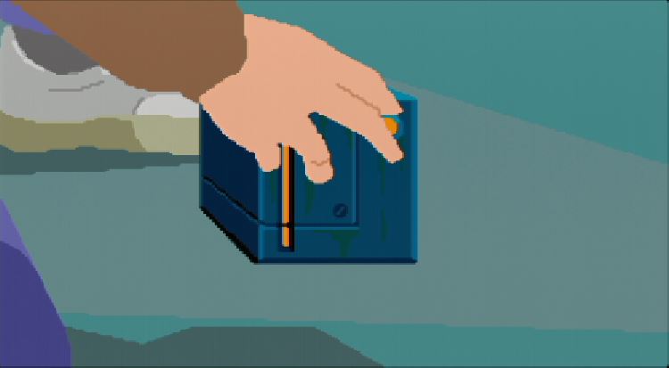
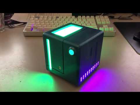
After watching a few play through on YouTube, I managed to build up enough stock images to identify what each side should look like. I was left with an unknown underside, however I’d need that for internal access anyway, so I left that side up to my imagination.
Side Note
The ANET A8 Printer can be made pretty decent, however as it comes it is dangerous and can burn your house down. Only get it if you are willing to work on it to make it safe and add upgrades, cheap is cheap for a reason, at the bare minimum, install Marlin with temp safety features, fix the heat bed contacts and consider an external MOSFET for the heated bed. However it may still burn your house down, you have been warned. Also you shouldn’t be operating 3D printers without them being supervised anyway.
Model Making
I had to make an assumption about the overall side of the cube, I made the rough estimate of about 10cm cubed. After handling the final product that actually feels about 1cm too big, however I’m glad I went that side for build reasons. Taking the many stills, measuring by pixel and assuming sizes, I was able to come up with some sensible dimensions.
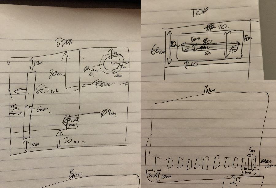
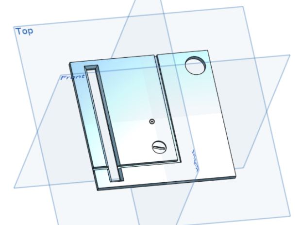
Once I had these I could attempt to turn the shape I’d only seen in a game into a model, since I got my 3D printer I’d been using Onshape, while I’m not currently convinced of their license scheme, it worked very well. I was able to produce something which seemed right.
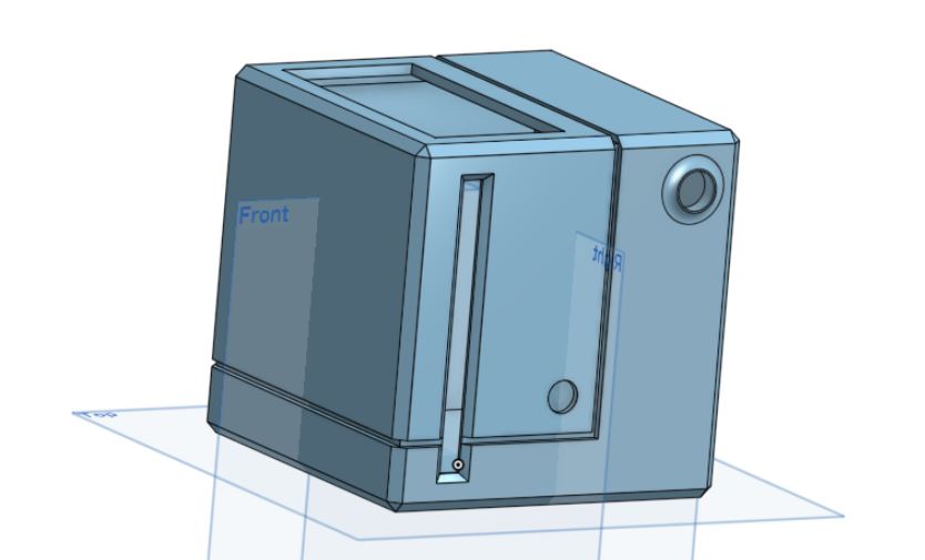
This looked great, and was pretty much what I wanted… except… how do I fit it out… wait… how do I print that? I did a miniature print (2.5cm cubed), I’d forgotten the bottom door, but then it needed to use support material to hold the roof up and similar. This wasn’t going to work. I “destructively queried” the printed model to get an understanding of how to print properly.
Doing this project I’ve learnt so much about thinking about assembly. Take two, I decided to print a skeleton, and each side separately. This meant that I’d be able use the flat hotbed of the printer to support all the large flat planes.
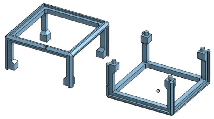
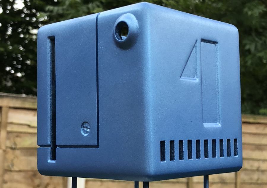
Printing and assembling!
After about six hours of printing, I had a real work representation of the cube. At least in blank white plastic. I glued the two frames together with an two part epoxy glue, and sanded the side panels so they’d at least fit in. I was starting to have something that looked like the cube.
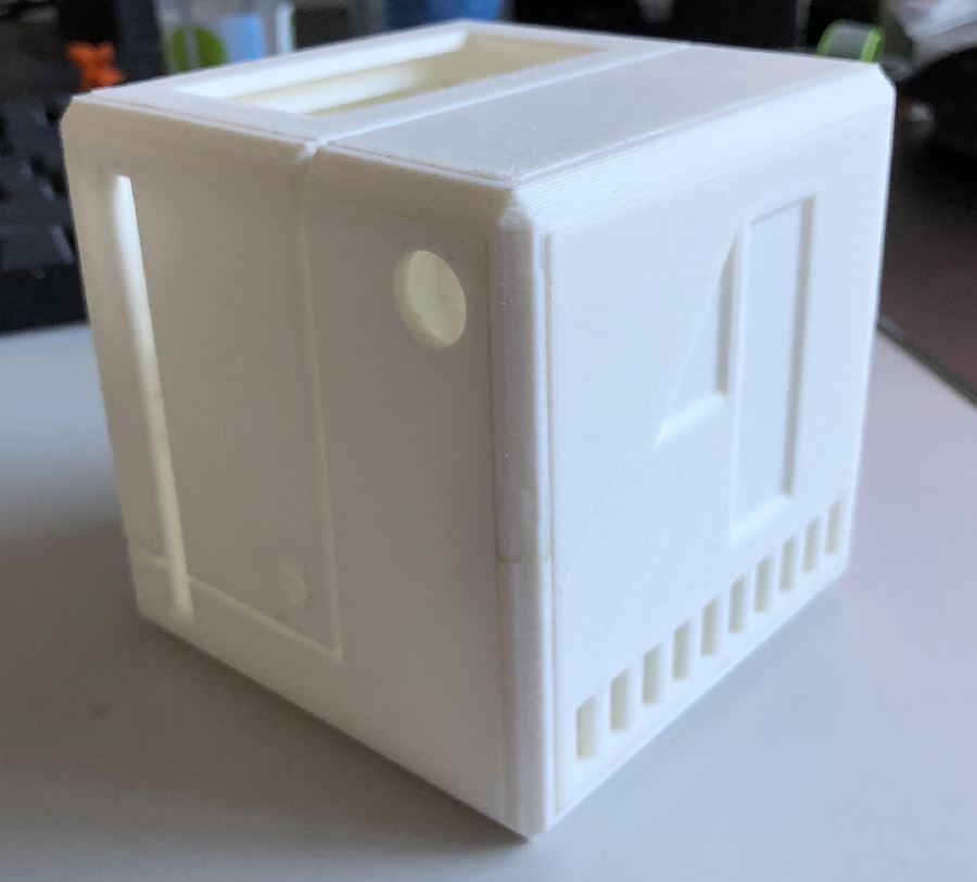
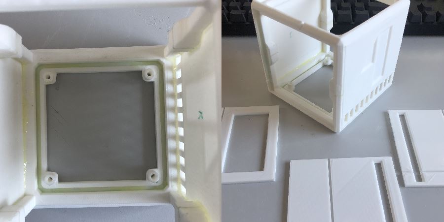
It looked very rough at this point, the plastic sides didn’t sit flush and I had to use a large amount of force to get the pieces in place. So, out came the sand paper! Sanding the side of each panel to enable an easy fit.
Sometimes I had to actually sand too much to allow the detail lines around the outside to match up, which left gaps. I also had to sand the back of the side panels, as otherwise I could not get them to sit flush with the frame. Tolerances on my 3D printer…. are not great.
However, eventually things started to fit. So it was time to start the assembly of the cube. Once again more epoxy glue, lots and lots of glue.
“If one only remembers to turn on the light”…
I could have statically painted this model to just be a off cube, or maybe a cube that was “on”. However, that wouldn’t have satisfied me. I wondered about static LEDs, that could have been one static colour. That would have worked, however it was less…. interesting, and the cube was animated in the game, so why not replicate?
Somehow I remembered about a fancy kind of LED which could be sent data, and it would change colour. These are of course the WS2811 and APA-106 LEDs, so I found them on AliExpress and ordered a couple of hundred of each of the different types, specifically the 5mm width variety where the chip was built into the LEDs diffuser.
Once they arrived I got them on some breadboard and started to prod them. However the vast majority of code samples for them I could find were for Arduino. I’ve never been an Arduino user, for some reason I’ve always been drawn to the Microchip PICs, they were the first microcontroller I played with and I’ve never found a real reason to change. Sure, hobbyist library support isn’t nearly as good, but I just get on with them well.
I did managed to find the datasheets for the LEDs, and man, the timings are tight for certain parts. Even the microcontroller running at 64Mhz can find its self with maybe 5-10 instructions between changing the data pin for these LEDs. Suffice to say, I managed to implement my own PIC WS2811 code.
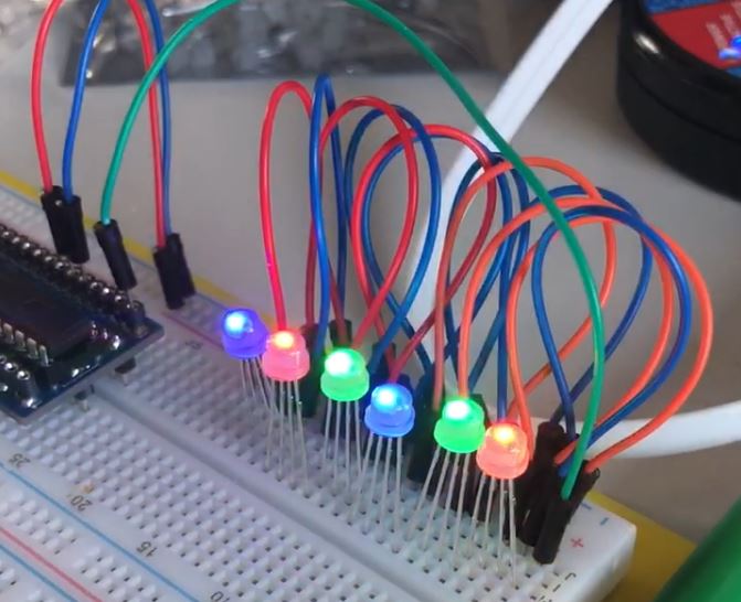
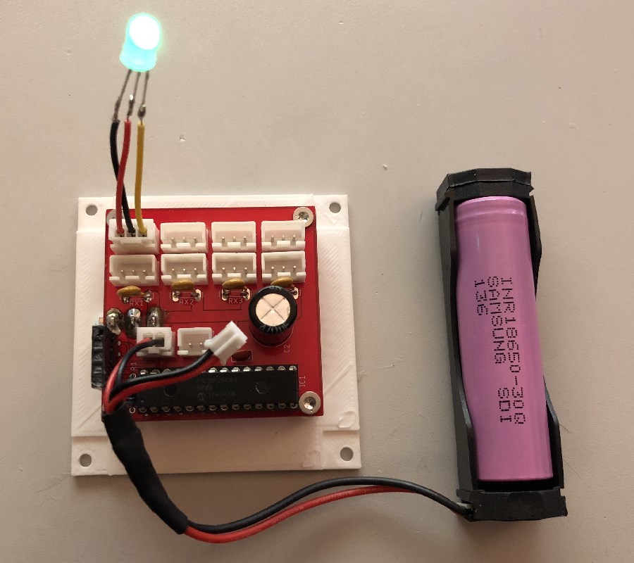
The PIC you can (just) see to the left is a PIC18F26K83 in my own inline debugger PCB, it’s a very overpowered PIC for this, but I have a bunch spare from a house alarm project that needs a CAN bus amongst other things. They also have peripheral pin select, which lets me assign different hardware peripherals to different pins.
So, now I’m ready to put something together to power the HoloCube, I considered initially just using veroboard, however I wanted to use some connectors (such as the JST-XH’s for power, button and LEDs) which didn’t map well to veroboards spacing.
I had to decide what features my board wanted, given the LEDs are effectively addressable, I only needed one LED output. However, if I was going to print a PCB I knew I’d get 10 back, so I wanted this to be usable for future projects.
I decided to provide four LED channel banks, in the future these could be used for anything else, as the pins they go back to can be set input or output. I decided on a channel for the side button, the side glowing sides, the rear grills and the top plate. I also decided to double up on the connectors for each bank, this was very useful during debugging, and allowed the two side panels to use the same bank in parallel.
Another reason to break them into different channels was it permitted me to add a poly fuse on each bank, this was due to my intended construction for the LED light pipes, a dead short was a distinct possibility. This design saved my bacon a few times. I intended to power this from a 3000 mAh 18650 lithium-ion battery, which is capable of pushing far more amps out than I was comfortable without any protection.
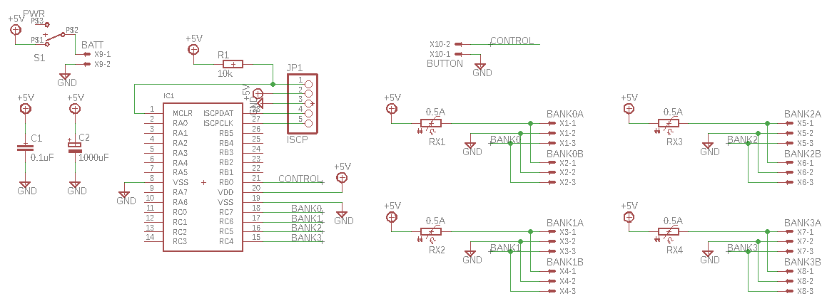
After adding a programming interface and a good chunky switch (rated for switching high current), I came up with the very basic circuit. One decision I stupidly made was to use the same connector for the battery as control button, I should have used a smaller connector for the button. I’ve never mixed the two up, but it could easily be done and could destroy the microcontroller.
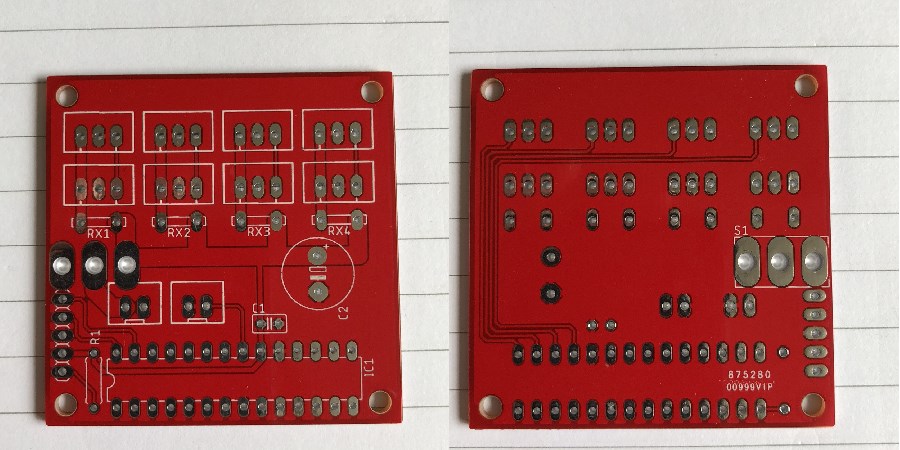
After some fiddling, I managed to come up with the following PCB design. Remembering to add mounting holes and only using the rear side of the board to carry the data signals and provide a ground plane.
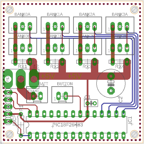
Looking at the design like this I’m sure you can see the possibility to confuse the button and battery, what’s worse is I’d connect the batteries positive to the ground plane too. Erk. Next time different connectors! The PIC also takes up a huge amount of room, a much smaller 64Mhz PIC would have done just fine. However the entire board is only 5cm x 5cm, without too much wasted room.
Sponsored Bit: SeeedStudio - Getting the board made!
SeeedStudio, the company I use to print PCBs, gave me a voucher to cover the cost of printing my next PCB if I blogged about the process. So, while I swear I’m telling the truth you can keep that in mind if you think I’m hailing corporate. I was always going to blog about creating the cube, and I’d have used SeeedStudio anyway, so it all made sense.
I first used SeeedStudio about 8 years ago when I wanted to do something unpleasant with a Sky TV box, ahum. It was the first PCB I’d ever had manufactured, in the end I never used the boards, but the result was good enough I was happy to give them another go. I had no relationship with them at the time, and they were the only reasonable choice for cheap PCBs shipping to the EU back then.
About six months ago, I started a project to replace my house alarm with my own creation, a project which is still on going, and still not complete due to my lack of understanding about building buck converter power supplies. Anyway, I built a version which used LM7805’s, which looked amazing and I was so happy with the board result. Just a shame they couldn’t provide enough power for the peripherals.
I posted the pictures on Twitter of the boards I’d had made for the alarm, Seeed liked what they saw and offered me this opportunity. Now… once I had decided to get a PCB made for the HoloCube, I’d have used SeeedStudio regardless of the voucher.
The fact I can get 10 PCBs of 10cm x 10cm made for $4.90, in a variety of colours, means it’d be my first choice anyway. There are no restrictions on the number of holes, or similar. The only rules they have are regarding panelization, which is not something I’ve ever needed.
I’ve always used EagleCAD (way before Autodesk brought them), given my hobbyist nature, I’ve never put aside the time to learn another package. I don’t have a huge fondness of Autodesk, I remember dealing with some very nasty licensing in a former life as an IT technician. But overall I’m happy with Eagle.
Anyway, once I had my PCB design, I downloaded the a DRC package (Design Rules Check) from Seeed (all documented on their website) which would validate that they could in fact print the board I had designed. Suffice to say, I’m not doing anything difficult, so it passed straight away.
They also provide you with a CAM script, instructions for EagleCAD on how to export the PCB design so that Seeed can produce it. After export you end up with a Gerber drill file, solder masks, silk screens and copper layouts for each side. Bundle up those files, upload via their website, pay and the job is submitted.
Now, if I have to complain about something, it’s the shipping options. From what I recall, they have few options, like DHL and FedEx, which are extremely expensive for a hobby job. Or they have a slow, but untraceable route via the traditional postal service.
My $4.90 HoloCube order, resulted in just over $30 for DHL shipping. Ouch. Thankfully the voucher they provided was $30, so effectively I still paid for my boards, they just shipped it for near free. I can’t help but feel there’s room for something in the middle here. I’d happily pay $10 for a traceable delivery of around a 5-10 days, especially for hobby work.
If they hadn’t given me a voucher, I’d have just taken the chance on the cheaper slower delivery (as I had before with no issues). Anyway, SeeedStudio manufactured the boards within five days (I didn’t request expedited manufacture). Shipping took 3 days, which still blows my mind how something can get from the other side of the world in that time.
They come in a small cardboard box, and inside that is a weird bubble wrap/vacuum pack pouch with your boards inside.
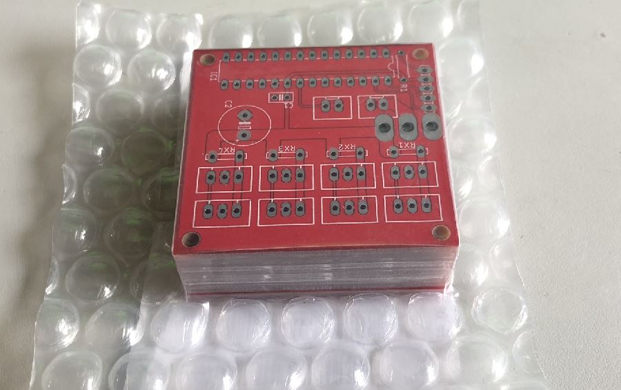
Suffice to say, all ten boards are basically flawless. The silkscreen is clear, it is made of dots, but there are no problems reading it. One downside of SeeedStudio which might be a deal breaker for you is they need to print the job number somewhere on your board. Their engineers do try and find a place for it under a component, or on the rear side (see the right had image in between the MCU pin arrays)
So if you fancy getting your own board printed, then you can head over the SeeedStudio’s Bazaar and get started with their Fusion PCB service.
What if you don’t fancy building the boards yourself? Well they also now have an assembly service where you can not only give them your PCB design, but also a bill of materials (from their library of 10,000 different components will be quicker, but they can source from DigiKey or Mouser) and a days later you can end up with a finished product!
I keep eyeing it up for a project, mostly because I hate SMD soldering. It’s called Fusion PCB Assembly and is worth a look, it’ll probably end up cheaper than you building your own if you’re doing more than a handful of boards!
Putting The First One Together
Having a bunch of empty boards does no one any good, time to populate one! I did only populate it with the minimum set initially to provide it worked, however I don’t have a picture of that.
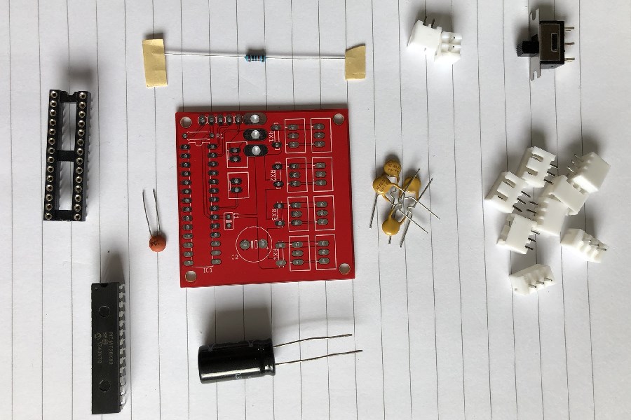
Very few passive components, a resistor for pulling up the MCLR reset line, decoupling capacitor for the MCU, tank capacitor for LEDs, and the 0.5A poly fuses for protection.
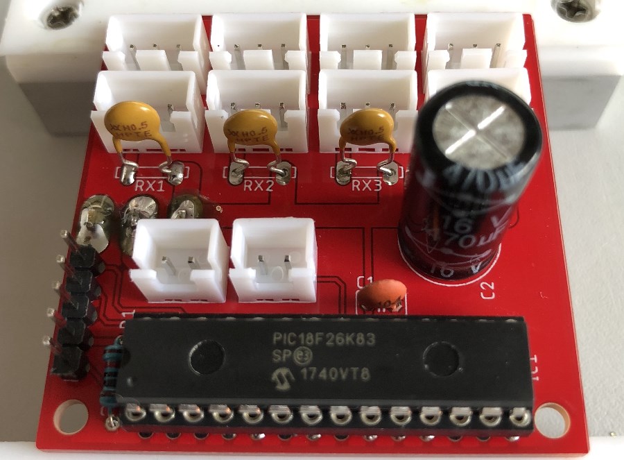
This picture was also before I noticed I hadn’t flowed solder properly into half of the MCU pins or fuse pins. I reflowed them all before it was fully assembled.
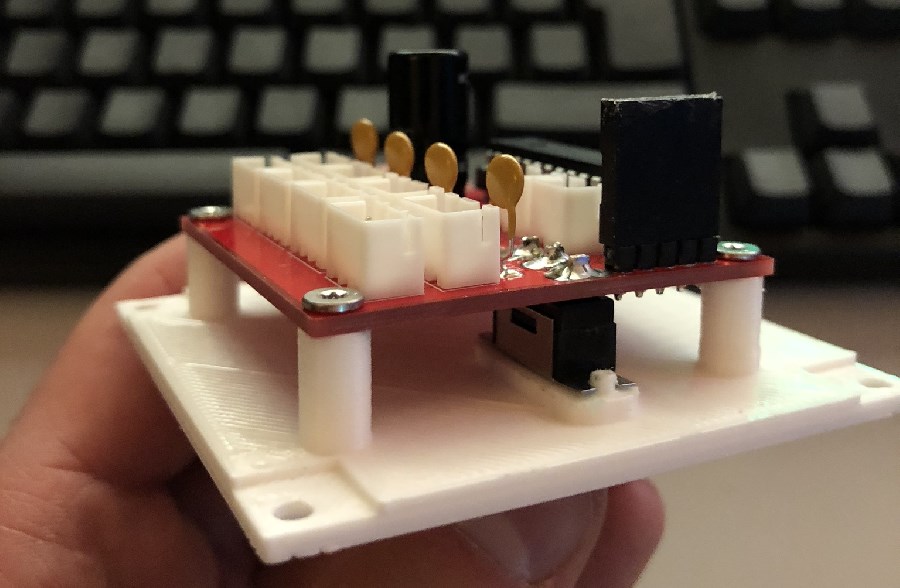
Mounted on the bottom door, mount for switch safely holding the switch with posts to prevent strain being put on PCB. I also manufactured a plug to cover the programming pins as an unfused 5V supply was available there!
So that’s the board, a big thanks to SeeedStudio for funding the board, as I say, I’d have used them anyway. I also have a use for the nine remaining boards, where I will be turning one of the bank outputs into an IR input. Maybe more on that project after they are used.
A quick note on power!
So, in the diagrams above and I think I’ve mentioned 5V, I’ve also mentioned an 18650, which is 3.7V. It turns out the PIC (no surprise, it’s 3.3V capable) and LEDs all operate happily at 3.7V, there was no visible difference between 3.7V and 5V. They did get visibly dimmer around 3.5V.
I’m also using unprotected 18650’s, however I did manage to find an 18650 holder that had a protection circuit in place. It prevented overcharging and overdischarge, reliably cutting out at 3.4V.
The Light Fantastic!
So, I had a case, I had a control board, it was time for getting the lights in place! First I approached the side lights, I initially took a rather naïve approach. I’d had the idea of getting transparent filament for the 3D printer so that I could make mounts for the LEDs.
So I printed a thin strip that I could mount the LEDs perpendicular to their face. That is, shining straight out. I’d realised I’d need to prevent light spilling out of the back of them, so spray painting them silver and then black saw an effective end to that. However… they looked bad, and not just on camera.
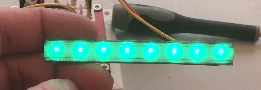
That…. was not going to work. So I had to figure out a way to defuse the light more, then it occurred to me I probably just needed to bounce the light internally of the light pipe. So I reprinted the mount, but with the LEDs side on to the face and a 45 degree angled surface to bounce the light off of.
This was so much better, it produced a solid and clean light. I connected the LEDs together by bending and soldering the legs together, the centre two providing VSS and VDD, and outer two weaving to provide data from output to input.
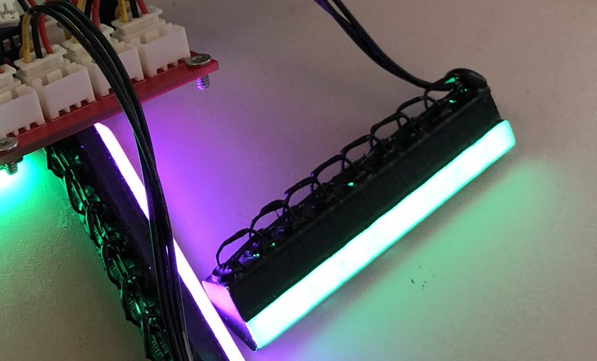
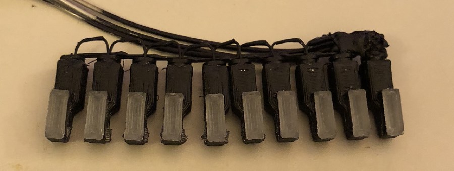
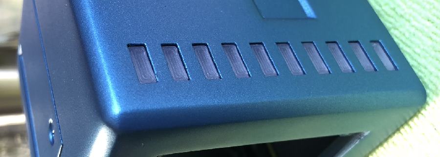
I replicated the same approach for the rear grill, however part of the animation requires lights to be individual, so I removed joining material after I had soldered the LEDs together.
I also then had to produce the top plate which was designed to be lit up strongly, in the game a hologram was emitted from the top of this. I feel this is the weakest area of the model, as I ran out of time and couldn’t perfect the light pipe design for it. The individual LEDs are actually visible through the top plate. Maybe one day I may come back and fix it.
Contact!
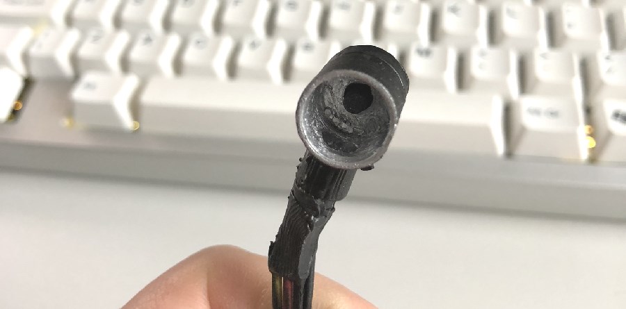
One of the bigger challenges for me was to figure out how to produce the glowing button. In the end, I produced a small tube with a micro switch at the end and an LED at 90 degrees which would project light into the tube which had been painted silver. A transparent button would then carry the light to the outside of the case.
The Body
Until now the cube it’s self was just glued together plastic which had gaps, wasn’t smooth, etc. Nowhere close to the finish I wanted. First I filled all the gaps, I used wood filler, in fact I generally smeared it everywhere over the model. Massaging it into any hole that would take it, any small imperfection that the 3D printer had made.

After the filler had set, out came the sand paper, 100, 200, 400, 1000, 2000. Working on 3D print lines and filled areas. I repeated both steps 3-4 times depending on what needed it. Sanding again and again. Eventually I got to a reasonable level of smoothness with just the 3D printed plastic and filler.
I had read that paint filler primer was useful for producing a smooth result, so I sprayed the case with several coats, let it set, and then sanding!
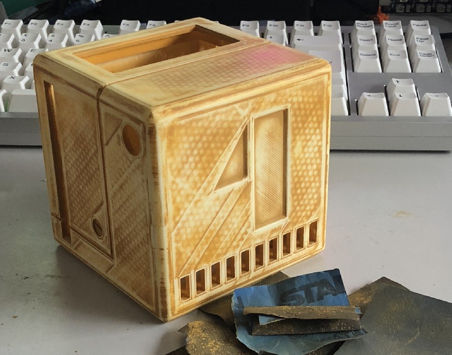
I oddly really like the effect that this shows, you can see the honey comb infill where the plastic has obviously sunk a little while printing. Again, this process was repeated another 2-3 times. So much sand paper! Also protip, don’t wet sand when you are using wood filler…. I have no further comment. So much work had to be redone.
I also needed to add a mound for the button. This was also 3D printed, added later and then wood filled. It still doesn’t look perfect, there were a few more priming’s and sanding’s, though taking less and less off each time. Eventually it reached the point in time that I’d have to just get on with it.
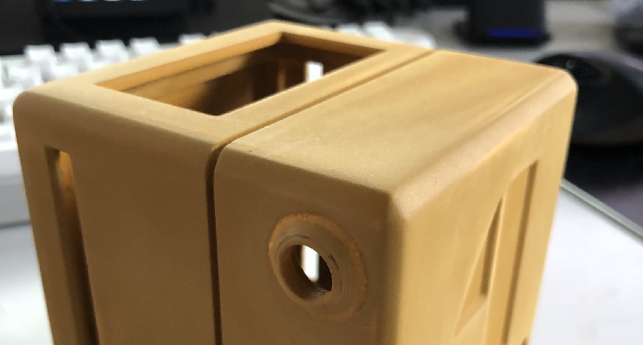
The colour of paint I wanted to use said to use a grey primer, however I couldn’t find a grey filler primer. So I thought I’d just paint it silver first, took a few coats. Some very light 2000 grit sanding occurred when needed.
Either by perfect planning or pure chance (I’ll let you decide), I reached a colour that was almost perfect for what I had envisaged. Again this was painted several times, which hid the final imperfections.
The paint work would eventually need lacquering to seal and give it some resistance to handling, but I would do that last, as it may also provide a seal between the LED light pipes and the case.
Also if I had thought about it, I would have cut a perfect circle and put it in the screw hole before I painted it blue. Instead I had to paint it by hand later.
Putting it all together.
The cube was painted, so it was time to put it all in. First I wanted to put the rear grill light pipes in, they were likely to be the most difficult due to glue curing and shape of light pipe. However surprisingly everything went in just fine. Again using 5 minute epoxy glue, I could hold the pipes exactly where they should be and allow them to set.
I proceeded to glue all the other light pipes in, one of the last things to go in was the battery holder. One thing I remembered to do was add a small ribbon around the battery, this made changing the battery vastly easier.
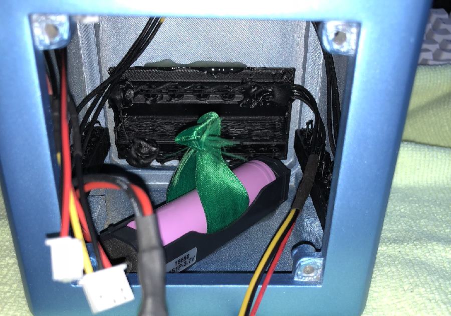
While you can see a splodge of epoxy, there was also a thin layer in the rim around the light pipes hole. The splodge was mostly there… “just in case”.
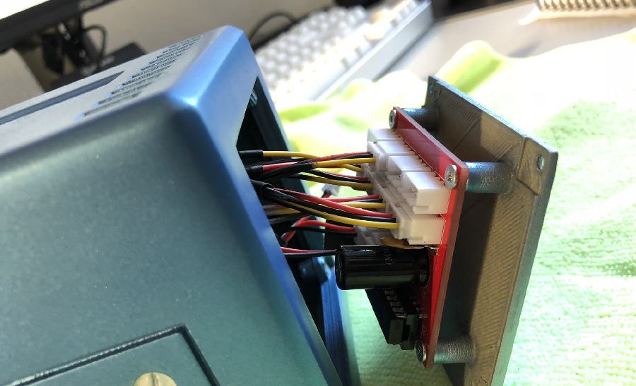
There was only just enough length on some of the wires from the side light pipes. After testing, the control board came out and the main body went off to be lacquered for multiple layers. I don’t think it’s technically dry yet, however dry enough to be handled.
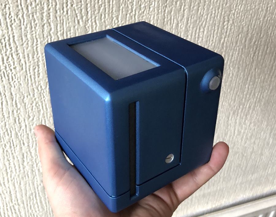
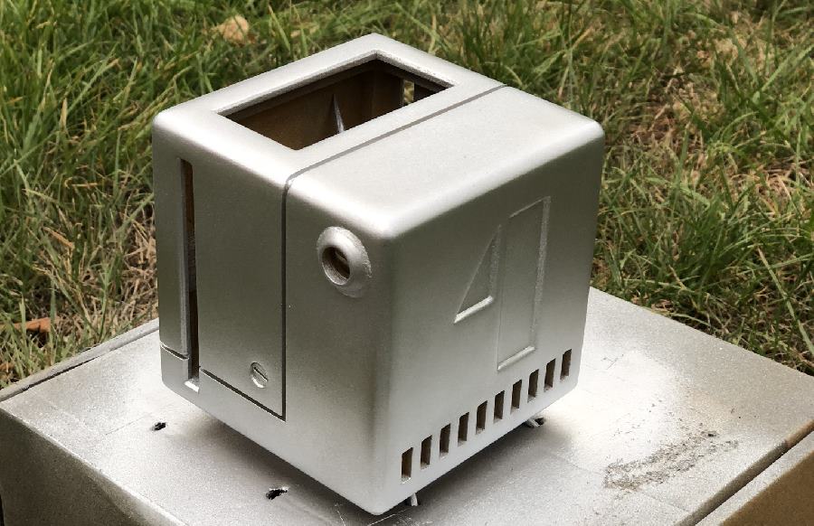
Et voila. A completed Holocube, I did managed to chip the paint around the button, however it actually just looks like weathering as it’s showing the silver base paint, looks just like metal.
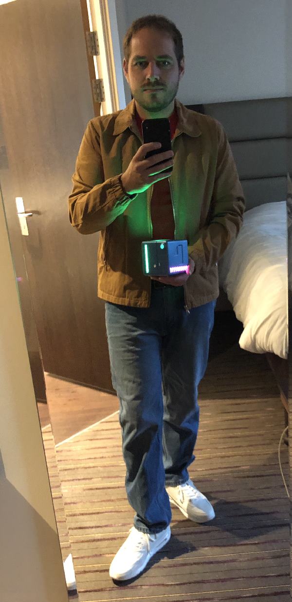
All together now.
I wouldn’t normally put this up there, but I guess I should show off the whole ensemble.
Animation
So from pictures it’s not clear why I needed a microcontroller, but I wanted to try and closely meet the animation from the 1992 game. So from what I’ve managed to enumerate from the game, this is what it looks like running! Click below for a YouTube video of the colour cycles.