So, over a year ago I blogged about having to hack into my home security system so that I could reconfigure it to work as I wanted to. At the end of that blog post I mentioned that I wanted to construct a computer interface to it.
My initial approach was to hook into the keypad network and attempt to gleam information from the messages flowing. After a few nights of looking at the data I gave it up as a bad job.
Then, very idly a few days ago I came across a GSM module for the alarm I have on eBay. I had expected it to plug into the communications interface (not present on my unit), but it didn’t, it wired into the standard alarm outputs.
I had initially ignored this approach as I’d preferred a more complete solution, but given reverse engineering the keypad protocol had escaped me (for now ;), it would do.
Alarm Theory
Most alarm panels have a large number of connections, predominately filled with zone connectors (those which go off to sensors).
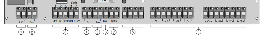
So, what information can we extract from these pins? The obvious place to start is section 3, those which connect to external sounders. In this case my panel has a Bell and Strobe output. Using these two we can actually tell if the alarm is, well, alarming.
When the alarm is triggered both Bell and Strobe will be active, causing the outside sounders to make a noise and to flash their light. Security alarms in the UK should silence themselves after 20 minutes, however they can continue to strobe if they have been triggered.
So with these two pins alone, I can tell when the alarm goes off and when it’s silenced.
That’s okay, but one of the other things I want to be able to check is if the system is armed. I want to be able to remind residents to turn it on in the evening if it’s not, or check from afar that I did in fact set it.
As it happens there is another connection, SW+ which can help us. It’s a configurable pin which is sometimes used for older sensors which need to latch when the alarm is armed.
Great, now we have a lot more information. We can also make a logical leap that if the sounder activated when the alarm is not armed, then either the alarm has detected it’s being tampered with or someone has pressed a panic button.
Another thing to know about alarm systems is that many signals are active when low, that is when the alarm does not want the outside bell to go off, it puts +12V on the Bell line. When it wants the bell to go off, it removes that voltage. This allows the outside bell to automatically trigger if it’s wiring is cut.
By default on my panel SW+ does not behave this way, but can be toggled and was so everything matched.
Hardware
Next up, we need an interface. The alarm signalling runs on 12V, 13.6V or 16.5V depending on if it’s regulated, battery charge voltage or unregulated. No microcontroller will take this.
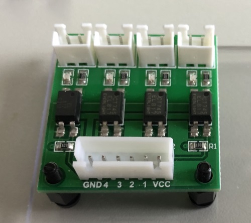
As it happens many optoisolators will, some take a large range of voltages. They also have the advantage they provide an air gap between the alarm and the monitoring system. Inside is a little light and a light sensor, separated by air.
From a security perspective they also mean that information should only travel one way.
The optoisolators are powered at the voltage you wish them to provide out on a positive signal. Also the configuration of the EL817’s on my breakout board invert the input signal, making it more logical to be read, armed will now be high rather then the alarms low.
Next I needed something to be able to receive these outputs, I thought about microcontrollers, maybe an ESP8266. However I wanted to store a history of alarm activations and trigger various other IP based notifications.
So out came a trusty Raspberry Pi Nano W. I’d never really used a Pi’s GPIO, sure the LED wall display does, but it’s not my code handling that. After some experimenting with “raspi-gpio” I felt confident it would work.
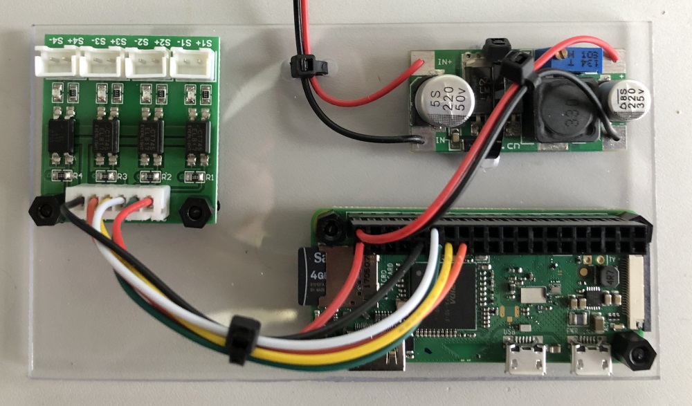
If you do anything like this, I’d advise you to buy yourself a crimp tool, some 2.54mm pitch crimps and the same DIL housings. It means you make a nice job of the board interconnects and makes it feel much higher quality.
Also mounting the components on a piece of acrylic gives you a nice solid foundation. Using the same nylon standoffs I had from the LED wall project everything is safe and secure. Unfortunately the voltage regulator does not have mounting holes so a single cable tie is used.
Once the voltage regulator was configured, a dab of rubber cement over the variable resistor ensures that it can’t be knocked accidentally. Also note once again the power supply to the Pi is bypassing it’s 5Vdc regulation, so you need to be sure the regulator is working as expected.
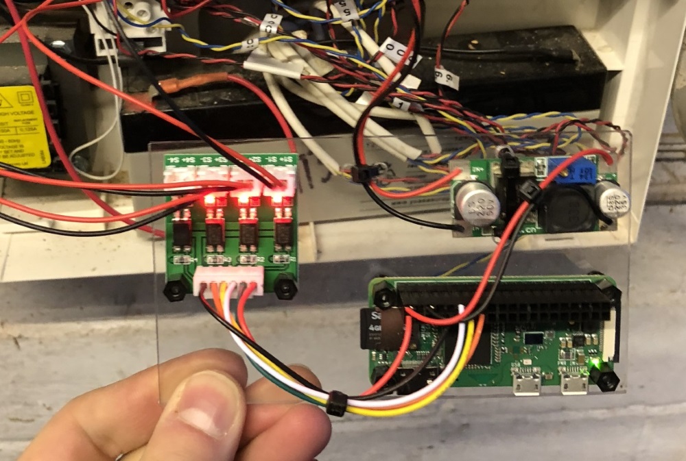
Yes, I know the inside of the alarm is a mess, no I didn’t do it. Yes, I have plans to tidy it up. Most alarms have a 12V auxiliary output, used to power PIRs and other active sensors. Wiring the regulator into this brought the Pi to life.
You can also see the high signals coming from the alarm, indicating that nothing is currently in alarm. The board is then placed against the battery and the alarm put back together.
Software
The hardware was the easy bit, most of it just a bit of soldering and cable crimping. Next is the software to monitor it, before I put the Pi in the alarm it had Raspbian headless installed on it and was joined to WiFi.
Most examples for Pi GPIO I see are written in Python, not my favourite language however I can use it. However I wanted to include a REST server and make some REST calls in case of alarm. I considered Ruby and looked at the Pi GPIO library that was available.
However in the end I decided to go with Java, yes the JVM works (well) on a Pi. Sure, it wont do great number crunching, but for passive applications it works. In fact now this is running, the JVM sits at 0.3% CPU monitoring GPIO, only spiking up for interaction with the world.
For GPIO and Java I found Pi4J a decent implementation which follows some good design patterns. Including interfaces to allow mocking/development, registering call backs for GPIO changes (yay no polling).
A couple of hours later, with JAX-RS, Glashfish, Unirest, Pi4J, H2 and Flyway I had an REST API which could return the current status and the history of the last fifty alarm state changes.
{
  "state": "UNARMED",
  "alarm": {
    "armed": false,
    "sounding": false,
    "strobing": false
  }
}
My alarm state machine allows registering a call back for state changes, which meant that adding a plug in to Pushover for remote notifications was trivial.
Risks
So, this isn’t without risk. I’m attaching something which can be remotely controlled to a system which is traditionally air gapped. What did I consider, what could happen, do I care?
If you think there’s something I’ve missed stupidly, send me a message on Twitter.
Connection to Alarm
The physical interface to the alarm panel connects only to outputs to other peripherals. If you could output 12V onto those lines, then the outside sounders would never trigger.
Mitigating this via optoisolators ensures that there is no electrical connection between the interface and the alarm. So it’s not possible to inject the 12V, further the interface board is only 3.3V, which is likely a low to alarm peripherals anyway.
The optoisolators will break down at 5kV AC (after more then a minute), however generating that from the Pi hardware (via software) is very unlikely.
Power Source
The Pi’s voltage regulator is connected to the auxiliary power output from the alarm. The auxiliary output is produced separately from that which feeds the outputs, alarm MCU and it is fused separately.
You could in theory use the Pi to try and draw too much current, or maybe attempt some kind of timing attack by greying out the power supply. However everything is very well decoupled, so it’s unlikely.
The most probable attack would be to try to blow the fuse that feeds the auxiliary output, at which point the alarm system will go into alarm.
Attack WiFi
The Pi is connected to WiFi, and an deauthentication attack could be leveraged against it. This would remove the ability for it to notify, however it would still record.
Given this is an informational service (and will not trigger police action) I’m happy to accept this risk. It’s unlikely a thief would even know this is present.
I could move this project to Ethernet with a dongle or different Pi, removing this risk. A different mitigation would be to bring a USB GSM modem into the mix, and use it to send SMS’ if system could not trigger Pushover. (BT RedCare often has a GSM fallback.)
Compromise
This to me is the biggest risk, if you managed to get through the various layers of defence this device lives behind, you would be able to extract information about when we are likely to be at home, or when the alarm is set.
I’m not going to talk specifically about mitigation to IP attacks. Suffice to say my home network is better secured then most businesses and I take further measures with sensitive devices.
Conclusion
All together a nice Saturday project, completed start to finish. The main extension I want to do is pestering users to arm the alarm.
Another possible extension, however will need a lot of thought is being able to set the alarm via the API. Zones can be configured as key switches which can set/unset the alarm, so I’d need some incorruptible hardware logic to ensure it can only set.