The Idea
So I was idly browsing AliExpress, not even sure why. When I came across some high definition LED panels (64x32 RGB LEDs) and I was stuck by the desire to make something bigger and better then my La Metric smart clock (at least for display).
The La Metric is neat, it’s insanely easy to use API is nice, but it’s really only 38x8 pixels, and only the first 8x8 are RGB.
After doing a rather large amount of research on these panels (a bunch of URLs I found useful at the end of this article), it turns out their interface is known as HUB 75.
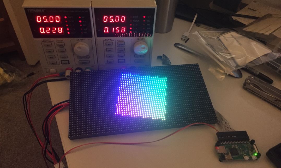
The panel is this one, a 4mm pitch 64x32, they are really designed to be driven by FPGAs in large TVs. The type you see on the side of buildings or trucks. I has initially imagined having to program a PIC18 to control the panel, it turns out others before me had the same idea.
The smarter ones found out that that a Raspberry Pi has enough CPU grunt (uses about 70%) to drive these screens at a reasonable refresh rate. Really you do still need a FPGA to really do them justice, but it’s still very good on the Pi.
These displays are chained together, each display having an input and an output. So I can have two panels for 128x32! I was tempted by three, but that would have been a little excessive (and tight on the next section).
Mounting
So if this is going to compete with the La Metric it’s going to need to look good, I could bodge it, but let’s do it well. So if we can mount the panels with nothing else showing, then it should look pretty decent.
After many years of pondering and almost clicking “Go”, I’m finally getting some bits laser cut. Using Razorlab who seem to be kinda related to Ponoko.
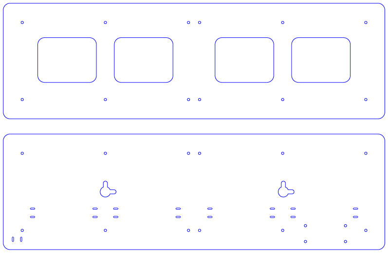
It’s being cut out of 3mm black acrylic. The first sheet holds the LED panels, there are no other holes or marks, meaning it can be mounted either landscape or portrait.
Using some nylon standoffs I found on amazon, I should be able to mount LED panels from the reverse. They are like motherboard standoffs, but nylon. I didn’t want to use anything which could easily crack the acrylic.
The second sheet is the back plate, it has a position for the Raspberry Pi Zero W. It also has holes for cable ties to keep things tidy, and finally hanging holes to make it easy to put on a wall.
That sheet should be screw-able into the standoffs used to hole the LED panels in place.
Wiring
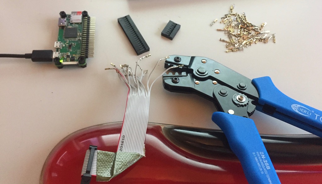
The wiring is a royal pain to do, the Pi GPIO connector is obviously not designed to directly take the HUB 75 connector. I thought about a few different methods, but I settled on making a bespoke connector for the GPIO port.
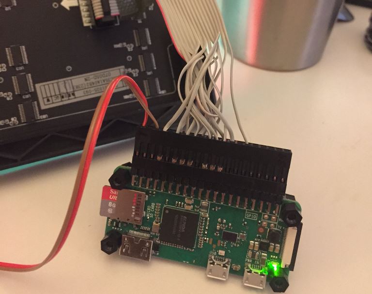
The Pi has a right angled port to allow a low profile between the two acrylic cut outs. You can also see some of the nylon standoffs already installed on the Pi.
Buying these bits is surprisingly tricky in the UK, however I’ve found that while Toby website looks dated they have those difficult to find parts for a reasonable price. Also a cheap crimping tool off of Amazon.
It doesn’t look the neatest, and I’ve had to sacrifice the cable that came with the LED panel, but it’s going to be secure.
The observant of you might notice that the Pi has no input in the USB power port. This is because I’m back feeding the power supply via the GPIO header. While it’s not really supported, if your 5V supply is rock solid then you can get away with it.
I actually had issues because of my bench supply. Initially I had them powered from the same channel, however when the LEDs kicked in the bench supply didn’t compensate quick enough and the voltage level dropped which reset the Pi.
The normal USB input does not have this problem, and I could solve it with a capacitor and low forward drop diode on the GPIO 5V input. I’ve also seen people recommending adding a large capacitor across each panels power input. This might also help smooth some of the initial rush until the PSU adapts.
To Be Continued
So now I wait for a second panel to clear customs, and for my acrylic to be cut so I can professionally mount it.
Then it’s software, I’d like to create an interface which let’s me split the panel up into sections and then independently render things there. With pages and other similar things.
I spend must of my life in the JVM, so I’m kinda tempted to write a library which allows interaction with the real hardware (yes, JNI).
I shall write another update once more has arrived!
Resources
- https://www.aliexpress.com/item/32x64-P4-Outdoor-SMD-RGB-full-color-LED-display-module-high-resolution-Indoor-1-16-scan/32575409827.html
- https://github.com/hzeller/rpi-rgb-led-matrix
- http://www.rayslogic.com/propeller/programming/AdafruitRGB/AdafruitRGB.htm
- https://www.adafruit.com/product/420
- https://learn.adafruit.com/32x16-32x32-rgb-led-matrix/
- https://www.amazon.co.uk/260pcs-Black-Spacers-Stand-off-Assortment/dp/B01GVD146I